
The application of control panel development in DC brushless motors
Publish Time:
2023-09-25
Brushless DC Motor - System Functions:

I. Brushless DC Motor - System Functions:
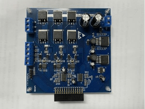
*Input voltage is DC24V/5A, with a pluggable 5.08 terminal interface;
*Requires a 3-digit digital display to show the set working time, in minutes;
*Requires a 24V/3A bidirectional DC motor control module with stall current detection, with a pluggable 5.08 terminal interface;
*Requires a 24V/3A unidirectional DC motor control module, with a pluggable 5.08 terminal interface;
*Requires a 24V/0.3A buzzer control module, with a pluggable 5.08 terminal interface;
*Requires two proximity switch input signals to control the A and B point positions;
*Requires a start button input signal to control the system on and off;
*Requires a reset button input signal to control the bidirectional DC motor to position A;
*Requires two potentiometer adjustment switches to set the working time of the two motors;
*Has data storage function;
II. Brushless DC Motor - Software Requirements:
*Start button: Turns the control system on and off;
*Reset button: The first set of bidirectional DC motors automatically resets to position A;
* Potentiometer: Adjusts the working time of the two motors;
*Proximity switch: Limits the bidirectional motor operation within points A and B;
*First set of bidirectional motor operation process: Within the set time, it moves from point A to point B, then from point B to point A, reciprocating;
*Second set of unidirectional motor operation process: The motor operates within the set time, and stops after reaching the set time;
*Buzzer alarm: 1. Alarms after the first set of bidirectional motors reach the set time; 2. Alarms when the first set of bidirectional motors reach stall protection; Alarm time is about 5 seconds.
*Stall protection: When the current of the bidirectional DC motor exceeds the set value, the stall protection is activated, both DC motors stop working, and the buzzer alarms; the stall current can be set.
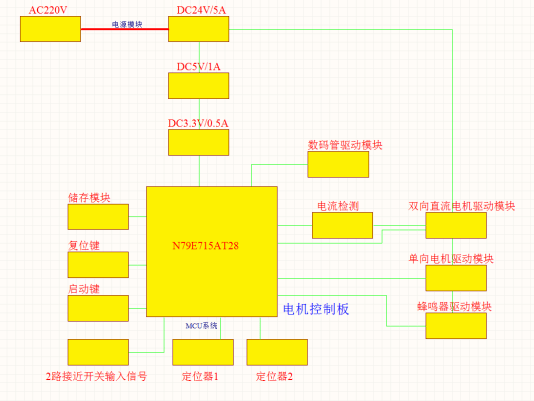
III. Brushless DC Motor - Functional Module Diagram:
Recommended news


